1. Emergency Response Workflow
Reactive maintenance is triggered when a live fiber network experiences an unplanned outage or degradation. Unlike scheduled maintenance, you don't control the timing — the incident controls you. Speed and methodology are everything.
1.1 Ticket Types & Response Priority
All field tickets fall into one of three categories. Know the difference — it determines how fast you move.
| Type | Description | Response |
|---|---|---|
| Reactive | Service outage or customer down — any severity. SLA-driven, no delays. | Immediately — leave as soon as ticket is assigned |
| MW | Maintenance Window tickets — scheduled work such as cutovers, low-light troubleshooting, MOPs, upgrades, or any task that requires a pre-arranged time with dispatch/NOC. | At the scheduled time — confirm with dispatch in advance |
| Planned | Non-urgent work — route audit, splice re-do, enclosure cleanup, cable relocation, documentation updates. | At your convenience within the next few days |
Reactive tickets always take priority over everything else. If you're on a planned job and a reactive ticket comes in — stop, secure your work area, and go. SLA clock is running.
1.2 Reactive Response Flow
When a reactive ticket drops, this is your sequence — no hesitation:
- Receive ticket — Dispatch sends location, symptoms, and customer info. Read it on the move.
- Acknowledge & go — Confirm receipt, give ETA, and start driving. Don't wait — SLA is already ticking.
- Check your truck — Splicer, OTDR, VFL, spare cable, connectors, cleaver — all should already be loaded. If something is missing, communicate to dispatch immediately.
- Travel — Head to the site. Update dispatch if traffic or conditions change your ETA.
- Arrive & assess — On-site visual inspection. Look for obvious damage — dig marks, downed cable, damaged enclosures, hazards.
- Localize fault — Use OTDR, VFL, and power meter to pinpoint the break or loss event.
- Repair — Execute the fix (fusion splice, connector replacement, cable bypass).
- Test & verify — Check power at the NIU with VeEX. If within operating range — repair is good. If not — OTDR again and find the next issue. Confirm service restoration with NOC before packing up.
- Document — Complete incident report, attach photos, submit to dispatch before leaving the area.
2. Dispatch & Arrival Procedures
2.1 Emergency Kit Contents
Your truck must be pre-loaded with the following at all times:
Test Equipment
- • OTDR (battery charged, launch cable attached)
- • Optical power meter + calibrated light source
- • Visual fault locator (VFL)
- • Tone generator and probe
Repair Supplies
- • Portable fusion splicer + splice sleeves
- • Extra splice sleeves (60 mm)
- • Spare cable (matching fiber type & count)
- • Splice enclosures (dome and inline)
- • Connector cleaning supplies
Tools
- • Cable stripper set (jacket, buffer, coating)
- • Fiber cleaver
- • Cable cutter / shears
- • Duct tape, electrical tape, cable ties
- • Headlamp / work light
Safety
- • Safety vest, hard hat, safety glasses
- • Traffic cones / warning signs
- • Work gloves
- • First aid kit
- • Fire extinguisher
Fusion splicer
VeEX OTDR at NDP

Required PPE
2.2 On-Site Arrival Protocol
- Park safely — Use cones/signs if working near roadways. Activate hazard lights.
- Update dispatch — "On-site at [location], beginning assessment."
- Safety sweep — Check for electrical hazards, traffic, confined spaces, weather conditions.
- Visual inspection — Walk the immediate area. Look for dig activity, cut marks on conduit, storm damage, downed aerial cable, damaged enclosures.
- Talk to people — If construction workers are nearby, ask if they hit anything. If residents are present, ask when service went down.
3. Fault Localization Techniques
Before you can fix it, you have to find it. Use these techniques in order — start with the fastest methods and escalate as needed.
3.1 Visual Fault Locator (VFL)
Always start VFL from the NIU and trace outward. Best for: drops, short runs, splice closures, MST cans.
- Connect VFL at the NIU and look for red light leaking along the drop toward the MST
- The red laser will be visible at any break, tight bend, or bad splice
- In dark enclosures (MST, PLP), you can see VFL light escaping through cracked fiber or loose splice sleeves
- Effective range: up to ~5 km depending on fiber condition
- If VFL shows the drop is clean, move to MST and VFL the next segment (F3 distribution)
3.2 OTDR Testing

VeEX OTDR connected at NDP — reading -24.17 dBm
Best for: locating faults in long cable runs, measuring distance to break.
- Connect the OTDR via a launch cable (≥330 ft for singlemode) to avoid the dead zone.
- Set the OTDR range to match the expected cable length (use auto-range if unsure).
- Run a trace. Look for the end of the fiber — if it ends sooner than expected, you have a break.
- Compare to the saved baseline trace (from installation). Any new events = damage.
- Note the distance to the fault. Remember: OTDR measures fiber length (1–2% longer than cable/route length).
- If possible, test from both ends and average the two distance readings for better accuracy.
- Use the distance + GIS/route maps to locate the physical position of the fault.
Tip: A complete cable break will show all fibers ending at the same distance. If only some fibers are affected, the issue may be inside a splice closure where individual fibers were damaged — not a full cable cut.
3.3 Power Meter Testing
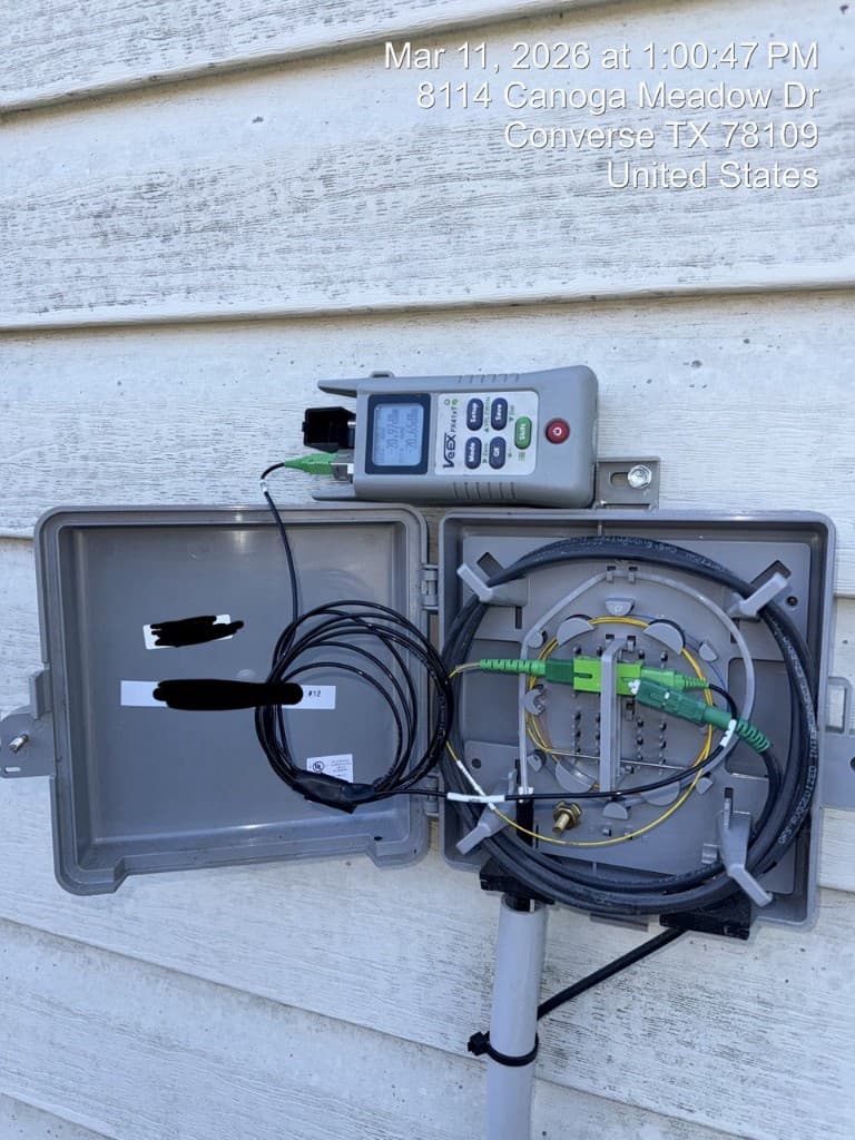
VeEX OPM measuring power at NIU
Measure power at the NIU first — this tells you whether the problem is in the cable plant or the electronics.
- Measure receive power at the NIU with VeEX. If zero → cable is broken or disconnected somewhere between NIU and the CO.
- If power is present at NIU but service is still down → electronics or protocol issue, escalate to NOC.
- If receive power is low but present → high-loss event somewhere in the path (dirty connector, bad splice, macro-bend). Use OTDR to locate it.
- Compare the reading to the acceptable operating range. If it's within spec, the cable plant is good — the issue is elsewhere.
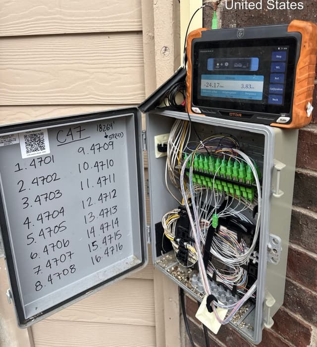
3.4 Tracing Strategy: NIU → F4 → F3 → F2 → F1
Always start from the NIU and work outward — from the smallest segment to the largest:
| Step | Tier | Segment | How to Test |
|---|---|---|---|
| 1 | NIU | Customer premises demarcation point. Your starting point. | VFL and power meter at the NIU |
| 2 | F4 — Drop | NIU → MST / terminal. 1–2 fiber drop cable. | VFL from NIU toward MST. OTDR if needed. |
| 3 | F3 — Distribution | MST → FDH / cabinet. Mid-count distribution cable. | OTDR from MST toward FDH |
| 4 | F2 — Feeder | FDH / cabinet → Fiber hut / CO. High fiber-count backbone cable. | OTDR from cabinet or hut |
| 5 | F1 — Backbone | CO → CO / headend interconnects. Core network infrastructure. | Escalate to NOC — usually not field tech scope |
Start at the NIU, VFL the drop (F4). If the drop is clean, move to F3 distribution, then F2 feeder. If the issue reaches F1 backbone level, escalate — that's a major event affecting many customers and is typically handled by NOC or a dedicated backbone crew.
We do not work from inside the customer's home or apartment. Always test from the NIU (outside the building). The only exception is when the NIU is inaccessible — then coordinate with dispatch for customer access.
4. Emergency Repair Methods
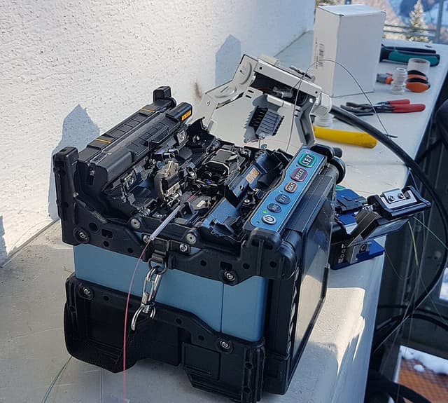
4.1 Fusion Splicing (Preferred)
Fusion splicing produces the lowest-loss, most reliable connection. Always preferred when time and conditions allow.
Fusion splicer in use
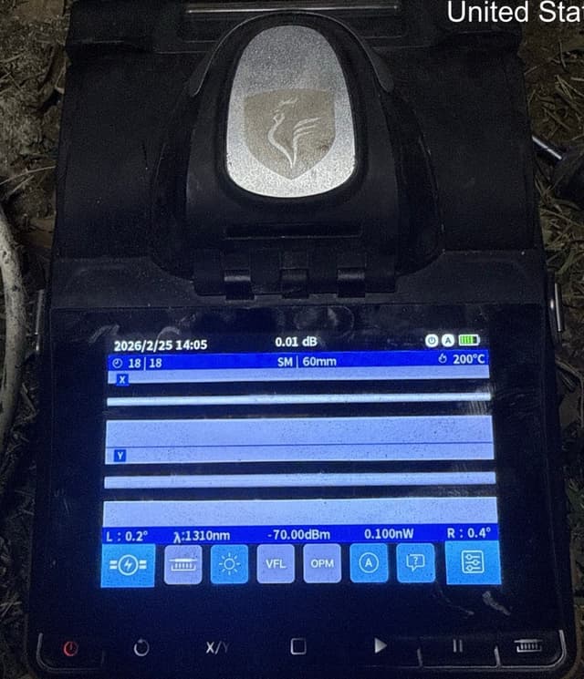
Splice result — 0.01 dB
- Expose enough fiber on both cable ends — cut back damaged section until you see clean, undamaged fiber. Leave ≥6 ft of cable on each side for working room.
- Strip the cable jacket, buffer tubes, and fiber coating per manufacturer specifications.
- Clean stripped fibers with lint-free wipes and 99% isopropyl alcohol.
- Cleave fibers to produce clean, flat end-faces. Inspect the cleave — reject and re-cleave if not clean.
- Load fibers into the fusion splicer. Align and fuse per splicer prompts.
- Target splice loss: ≤ 0.02 dB. Acceptable maximum: 0.1 dB.
- Apply heat-shrink splice sleeve to protect the splice point.
- Place spliced fibers into the splice tray. Maintain minimum bend radius at all times.
- Repeat for all fibers in the cable.
4.2 Connector Repair
If the fault is a bad connector (at a patch panel, MST, or NDP):
- Visually inspect the connector ferrule for obvious damage (scratches, chips, cracks).
- Clean using a one-click cleaner or lint-free wipe with IPA. Re-inspect.
- If the connector is physically damaged (cracked ferrule, broken boot), replace the patchcord or re-terminate.
- After cleaning/replacing, re-test light levels to confirm fix.
4.3 Temporary Bypass
In extreme reactive situations, if the damaged cable section cannot be repaired quickly and SLA demands immediate service restoration, a temporary bypass cable can be installed:
- Lay a temporary cable along a safe surface route between the two nearest access points
- Fusion splice into the existing fiber at both ends
- Protect the temporary cable from traffic and weather
- Mark clearly as TEMPORARY and schedule permanent repair ASAP
5. Post-Repair Testing & Verification
Never leave a site until testing confirms the repair is good. Use VeEX (or equivalent OTDR/power meter) to verify.
- Power meter check at NIU — After the repair, measure receive power at the NIU with VeEX. If the reading is within the acceptable operating range — the repair is good.
- Out of range? OTDR again — If power levels don't pass, the issue isn't fully resolved. Run OTDR from the repair point and trace further to find the remaining fault. Fix it and re-test. Repeat until power at the NIU is within spec.
- Service verification with NOC — Call dispatch/NOC and confirm the customer's service is restored. Wait for explicit confirmation before packing up.
- Physical inspection — Ensure all splice enclosures are sealed, all cable is supported properly, no loose fibers or tools left behind.
- Photo documentation — Take photos of the repair site, splice tray, enclosure, and any visible route changes.
The job is not done until VeEX shows acceptable power at the NIU. If the numbers don't pass — don't leave. OTDR again, find the next problem, fix it, re-test.
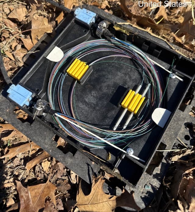
PLP — splice tray secured
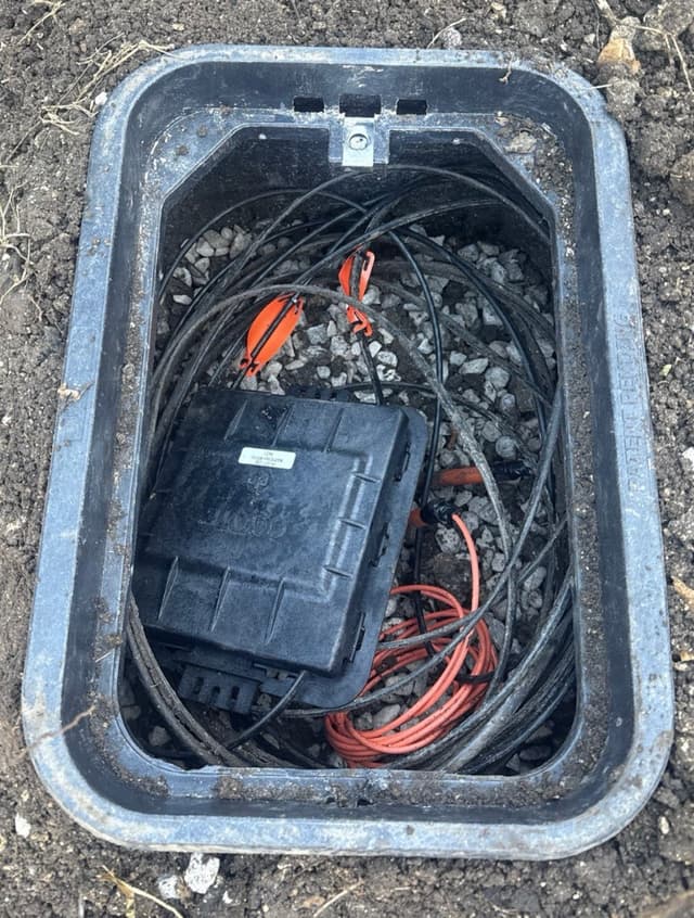
Vault — PLP inside
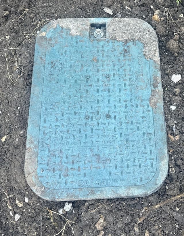
Vault lid bolted
6. Incident Documentation & Root Cause
6.1 Incident Report Fields
Submit a report to dispatch before leaving the area. Include:
- Ticket number and type (reactive / MW / planned)
- Date, time of dispatch, arrival, repair completion, service restoration
- Location (address + GPS coordinates)
- Description of the fault (what was broken, where in the network)
- Root cause (dig-up, storm, animal, equipment failure, human error, unknown)
- Repair method used (fusion splice, connector replacement, cable bypass)
- Test results: splice loss, end-to-end loss, receive power
- Permanent or temporary repair — if temporary, when permanent repair is planned
- Photos attached
6.2 Root Cause Analysis (RCA)
For reactive tickets, a formal RCA may be required by dispatch or the client. Common root causes:
Third-Party Dig-Up
Construction crew hit buried cable. Check 811 records — was the area marked?
Storm / Weather
Ice, wind, or fallen trees damaged aerial cable or flooded underground infrastructure.
Vehicle Accident
Vehicle struck a utility pole, pulling down aerial cable or damaging a pedestal.
Animal Damage
Rodents chewed through cable sheath. Common in aerial and underground installations.
Equipment Failure
Transmitter, receiver, or ONT/OLT failure — not a cable plant issue.
Human Error
Technician disconnected the wrong fiber, damaged fiber in a splice closure, or broke a patchcord.
Field Standards
LL thresholds, splice & connector criteria, attenuation tables